Hitachi M12V Springs
How to remove the springs of the Hitachi M12V. These instructions are strictly the opinions of the author and should not refer or reflect those of the manufacturer. Always refer to your owners manual for exploded views of your router and if you don't feel comfortable with these directions do not remove your springs.
Lock the plunge base on the M12V
Step 1: Lay the router on it's back with the threaded rod face up and lock it into position.
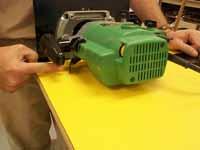
Position the lock down on the M12V
Step 2: Lay the router on it's back with the lock mechanism down to the table surface. See below image.
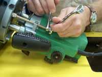
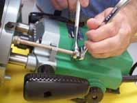
Release the threaded rod on the M12V
Step 3: Remove the two 13mm nuts that are at the top of the rod. See below image.
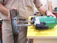
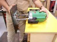
Release the spring tension on the M12V
Step 4: With your body against the base plate, and your hands on the router, release the lock mechanism. The base will press against you and will start to slide off. See below image.

Separate the base from the M12V
Step 5: When there is no pressure against you, grab the base and pull the base off. The springs will be hanging from the router. See below image.
Remove the springs and posts on the M12V
Step 6: Begin pulling the springs out of the body and as you pull, bend them down a bit. This will grab the two metal posts inside the springs. They are inside the springs to keep the springs from coiling up on them. See below image.

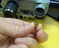
The small brass pin in the M12V
Step 7: Remove the springs and metal posts. NOTE (the lock mechanism is a small brass pin that cams out to lock the router in place and cams in to unlock it.) DO NOT LOSE THIS PIN OR YOUR ROUTER WILL NOT BE ABLE TO LOCK. This pin must be in place whether you are using your router with OR without the springs. The pin sits in a small hole about 1” in from the bottom of the column hole. It sits in the router like a barrel and is not attached. It has no left or right so if it comes out when you remove the springs remember to put it back into place before you put the columns back on. See below image.
Replace the base of the M12V
Step 8: Slide the base back into the router body. Make sure that the threaded rod slide over the horseshoe shaped body housing. With your router on it’s back and the lock down to the table, the long column should slide into the left side of the body and then slide the right side in. Do no force the short column into the router. (it should slide in easily) Keep your pressure on the long column as it slides in. This will allow the short one to slide in also. You may notice a lip on the router body that the short column slides into. Wiggle the base until the short column hits the hole. See below image.
Replace the rod on the M12V
Step 9: Once the base is in lock your router into place and turn it over with the threaded rod face up. Thread the two 13mm nuts over the threaded rod and turn them until they are about ľ” from the top of the rod. Lock them together so that they won’t vibrate off.